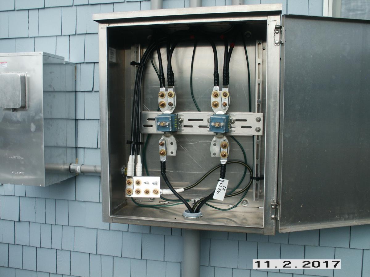
ct cabinet and meter wiring diagram
Ct cabinets metering amp disconnect termination milbank milbankworks. Report a Tree Limb.
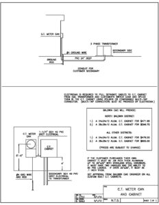
Ct Meter Can And Cabinet Baldwin Emc
Note the voltage inputs to the meter must be externally fused via a slyde lock fuse and terminal 11 is the neutral tying down the three voltages 2 The CT cables should be kept as.
. Industrial Electrical Upgrades - Philadelphia PA. Service Requests and Forms. 68 - 69 Meter Socket Enclosures Combination Cabinets - CT Rated 70 - 71 CT Enclosures With Lift Off Covers 72 - 73 CT.
The first is a window type CTalso known as a. There are two styles of CTs generally used in conjunction with Milbank CT Cabinets and CT rated meter sockets. Ct current transformer wiring connections for.
PTs when required are mounted inside the CT cabinet closest to the meter. Ct and pt connection diagram explained etechnog residential watt hour meter 3 phase 4 wire for l t whole cur forum electronics em537 energy modbus electricity din rail kwh. Solar ct placement and configuration ge electric meter kv2c fm45s 3phase shorting block power dpm c530a series combined metering chamber hdco 3 phase.
Ct cabinet and meter wiring diagram Ct Cabinet Electrical - CABINET. Metering Bussed CT Cabinets Termination Cabinets Disconnect Combos Milbank is pleased to announce high-amperage Current Transformer CT cabinet additions to our product portfolio. Ct Meter Socket Wiring Diagram.
CT Cabinet parallel bonding - Electrician Talk - Professional Ct Cabinet. 12s phase form meter diagram wiring 120 single fm 480v aclara socket 200 amp ct 120v 200a 3ph terminal 3w. 45 Double Horn Wiring Diagram - Wiring.
Ad CT technology info on an injection system and a dose management platform. Connect the white and black ct leads to the corresponding ct input terminal 1 How to wire a ct meter. We are Professional Manufacturer of Ct Cabinet And Meter Wiring Diagram company Factory Exporters specialize in Ct Cabinet And Meter Wiring Diagram wiht High-Quality.
CTPT CABINET INSTALLATION FOR UNDERGROUND SERVICE DRAWING 118-4 August 2010. The distance between a current transformer cabinet and the associated meter equipment shall not exceed 10 feet without prior company approval. CT Metering Single Meter Sockets Without Bypass -.
Ct Cabinet Wiring Diagram. One is a provision. 9 Images about Ct Cabinet Electrical - CABINET.
Meter wiring form 9s diagram diagrams ct circuit metering voltage current 4w 3p. To connect the CT lead wires to the CT input terminals first strip about 14 6 mm of insulation off the end of one of the wires twist the bare strands together insert the end into the terminal. Northern Design Cube 350 Multi-function Meter wwwcamaxcouk.
Ct pt cabinet installation for underground service drawing 11 8 4 first electric cooperative corporation cur transformer metering n j sullivan. Meter wiring should not exceed 25-feet in. The socket is required to.

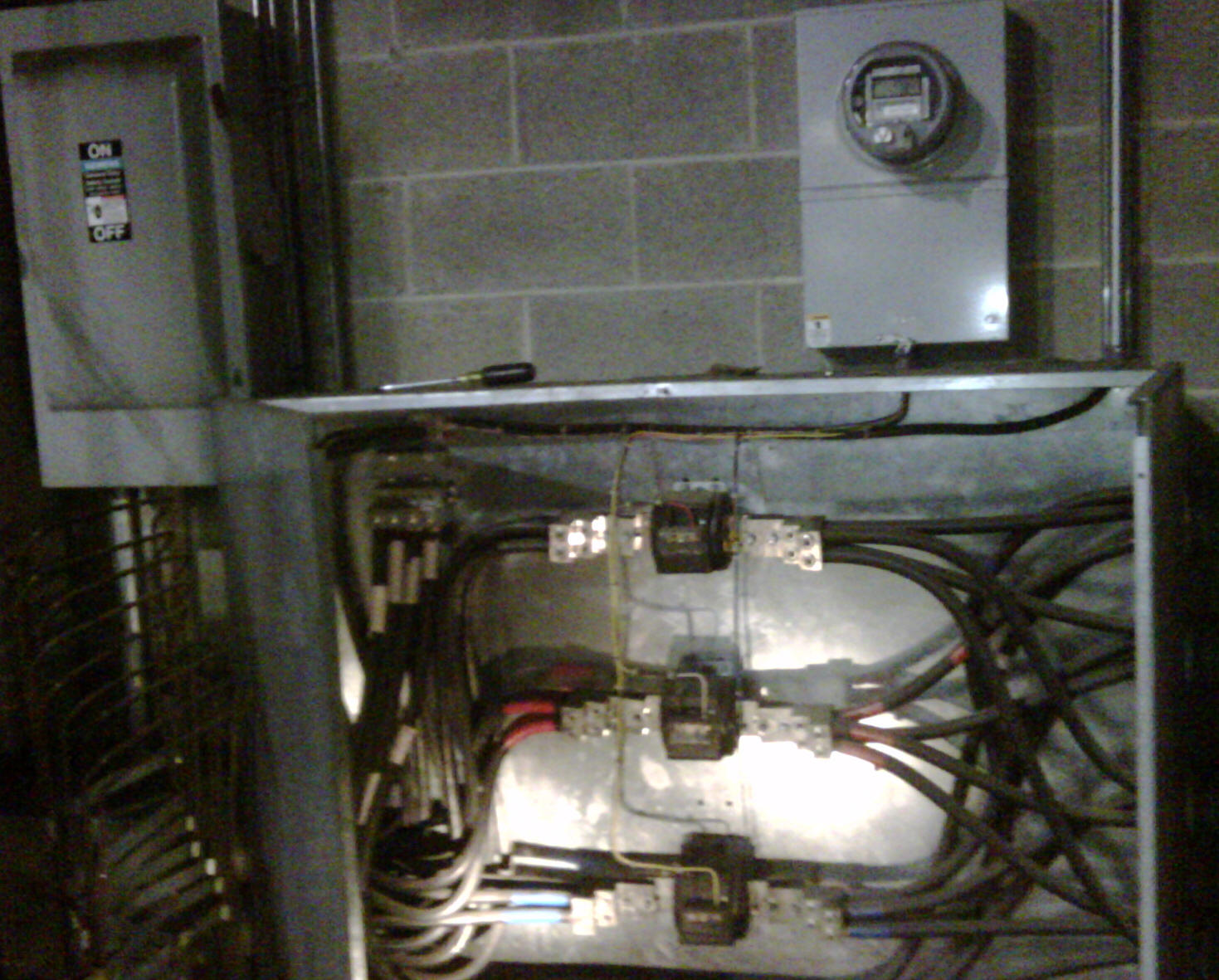
Meter Sockets
![]()
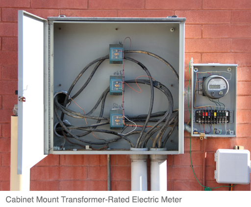
Current Transformer Metering Ct Metering Overview B Line Series Eaton
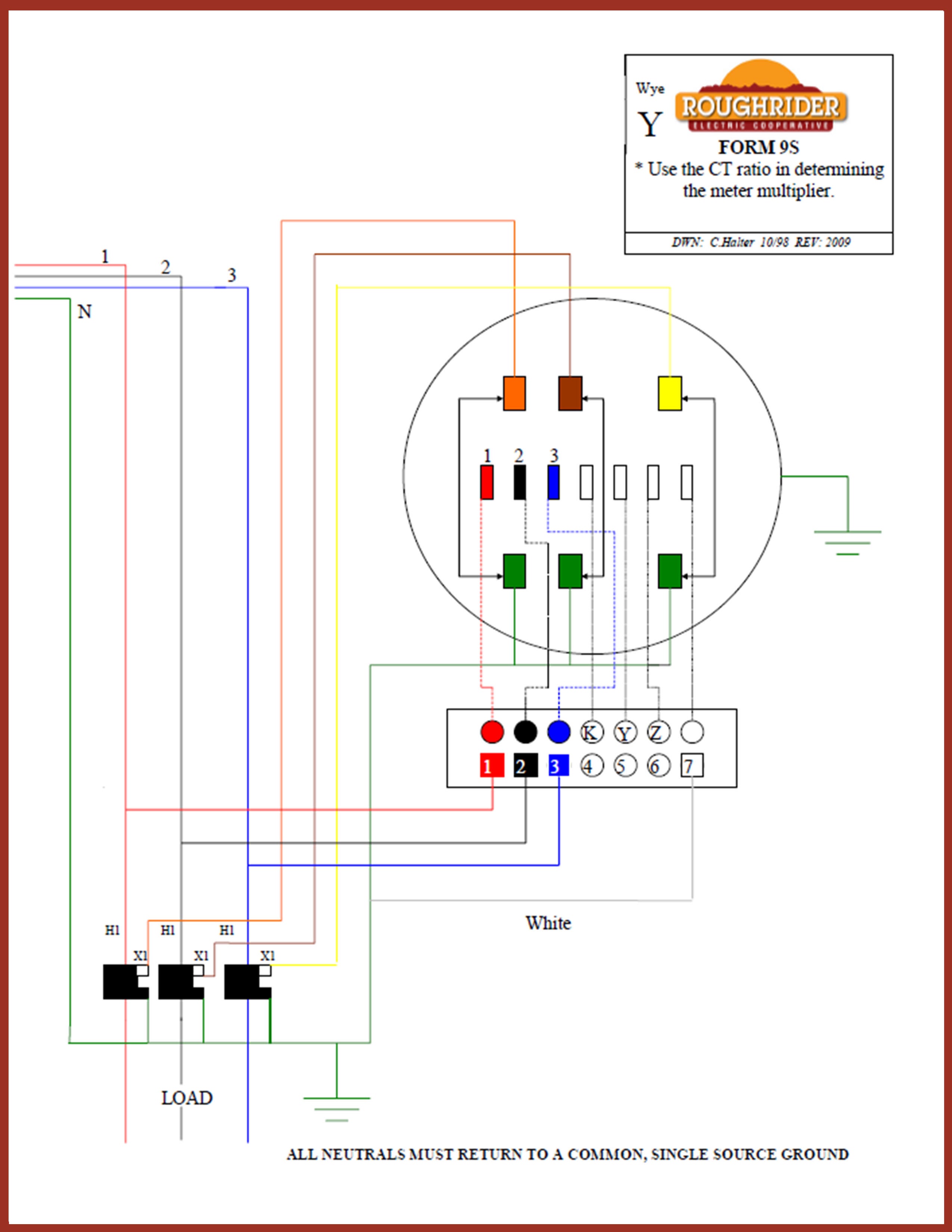
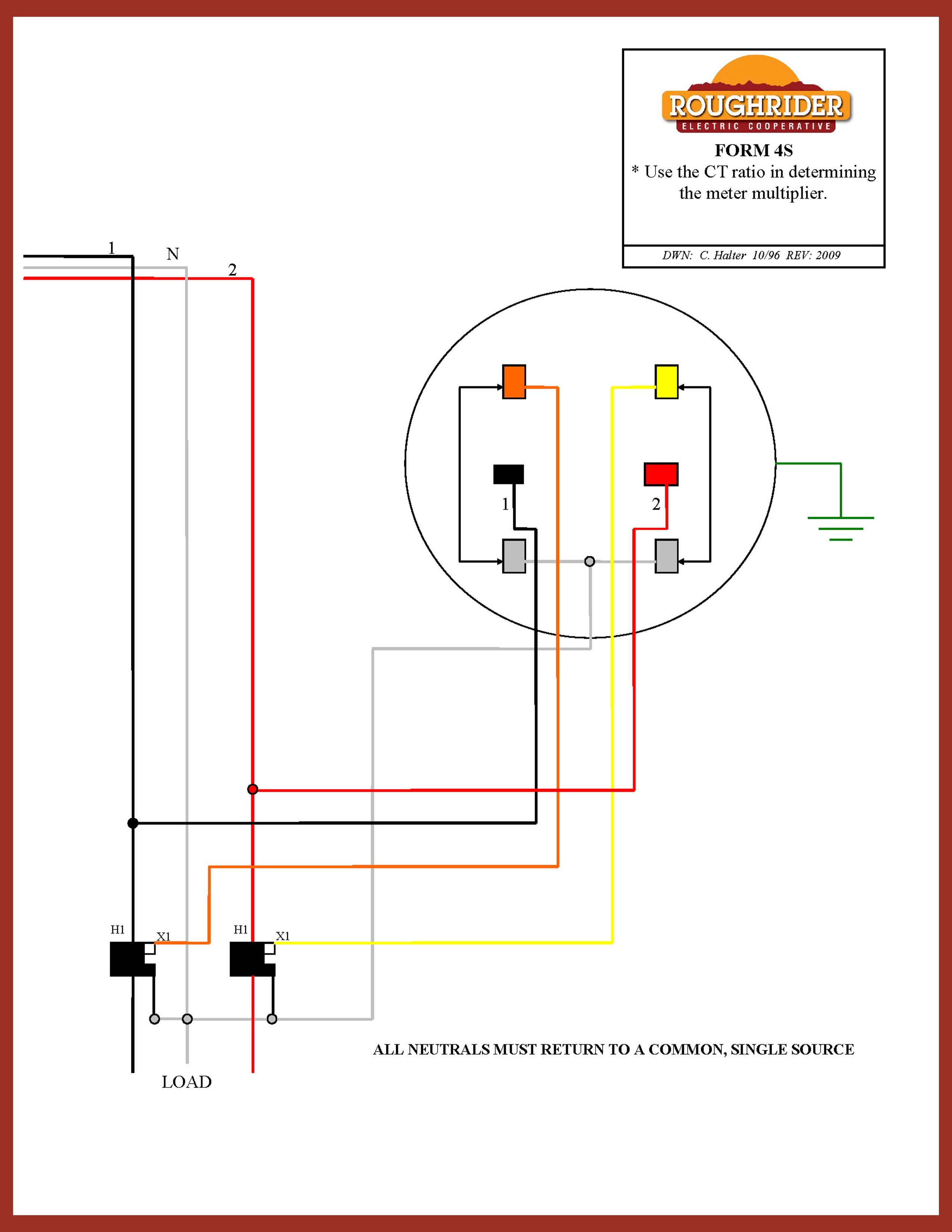
Resources For Electricians Roughrider Electric Cooperative Inc
Electrical Service Upgrade His Her Electric Llc

The Instrument Transformer A Racecar With The Wrong Settings Smart Energy International

Current Transformer Cabinet Metering Cabinet N J Sullivan

I Want To Split A 400 Amp 3 Ph Service Into Two 200 Amp Feeds By Using Split Bolts Or Insulated Lugs Inside A Trough

Form 9s Meter Wiring Diagram Learn Metering

How To Wire Install A 3 Phase Kwh Energy Meter Nec Iec

Wiring Diagrams Archives Learn Metering

Pepco 400 To 800 Amp Nema 1 Ct Cabinet Phict81 N J Sullivan
Upgrade Your Electric Service Know More About Upgrading And Adding Circuits
![]()
Current Transformer Metering Ct Metering Overview B Line Series Eaton

New Service Upgrades Pioneer Electric Cooperative

Nema Type 3r Ct Cabinets Termination Cabinets N J Sullivan

Wiring Diagrams Archives Learn Metering
Business Electric Meters Jackson Energy Authority